
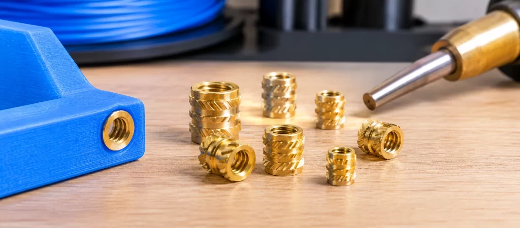
Brass heat-set inserts give 3D-printed and molded plastic parts strong, reusable metal threads. This guide from Anand Brass Components, a brass insert manufacturer, covers sizes, hole diameters, iron temperatures, installation, design rules and the fixes for common mistakes.
⚡ Quick Answer
What are heat-set inserts and how do you install them?
Heat-set inserts are small knurled brass bushings with internal threads. You press them into a hole in a plastic part with a heated tool, usually a soldering iron with a special tip. The plastic melts, flows into the knurls, and re-solidifies, locking the insert in place and giving you durable metal threads that can be screwed and unscrewed many times. Rules of thumb: model the hole slightly smaller than the insert’s outer diameter (for an M3 insert, typically about 4.0–4.2 mm), make a blind hole about 1 mm deeper than the insert, and set the iron about 10–20 °C above your print temperature (around 220–230 °C for PLA). Press straight down with light pressure, stop just below flush, and let it cool. Always check the hole size on your insert supplier’s datasheet, because designs vary.
🎯 Key takeaways
- Heat-set inserts beat threads tapped into plastic for strength, reuse and torque.
- Brass is the standard material: it conducts heat well, machines cleanly and doesn’t rust.
- The hole size is the most important number. Follow the datasheet and allow for printer tolerance.
- Temperature matters: too cold and the insert won’t sink, too hot and the plastic turns to goo.
- Wall thickness around the insert should be at least about 1.5–2× the insert’s outer diameter overall, or 3–4 perimeters in FDM prints.
- For production plastics, the same inserts go in by heat staking, ultrasonic insertion, press-fit or molding-in.
- M2–M6Most common metric insert sizes
- +10–20 °CIron temp above print temp
- ~1 mmExtra hole depth below the insert
- ~0.25 mmTypical undersize of printed holes
What are heat-set inserts?
A heat-set insert (also called a heat-staked insert, thermal insert or threaded insert for plastic) is a short cylinder, almost always brass, with:
- an internal thread (M2, M3, M4, #4-40, #6-32 and so on),
- an outer knurl pattern (straight, diamond, or opposing helical bands) that grips the plastic and resists pull-out and rotation,
- often a smooth pilot or lead-in at the bottom that centres the insert in the hole,
- sometimes a slight taper to match tapered holes in molded parts.
When the insert is heated and pressed in, the surrounding plastic softens and flows into the knurls and undercuts. When it cools, the insert is mechanically locked. The result is a threaded hole that behaves like metal: you can assemble and disassemble the part dozens of times without stripping it, which plastic threads can’t survive.
Heat-set inserts are everywhere: in 3D printer enclosures, drones, robotics, electronics housings, medical devices, automotive trim, consumer appliances and laptop cases. In molded parts they are installed by machines in milliseconds. In 3D printing, makers install them with a soldering iron.
Why are inserts made of brass?
- Thermal conductivity. Brass passes heat from the tool to the plastic quickly and evenly, so the insert melts its way in cleanly.
- Machinability. Free-cutting brass such as C36000 / CW614N machines into fine threads and sharp knurls at high speed, which keeps inserts affordable. See brass alloys for CNC machining.
- Corrosion resistance. Brass doesn’t rust, so threads stay clean in humid or outdoor products.
- Strength. Brass threads are far stronger than threads in PLA, ABS or nylon.
- Compliance options. Lead-free and low-lead brass grades are available for RoHS-sensitive or food-contact applications. See our lead-free brass guide.
Stainless steel and aluminium inserts exist for special cases, but brass dominates because it balances cost, heat transfer and machinability.
Types of threaded inserts for plastic
| Type | How it’s installed | Holding strength | Best for |
|---|---|---|---|
| Heat-set (thermal) | Heated tool melts plastic around the insert | High | 3D prints, thermoplastic moldings, low to high volume |
| Ultrasonic | Ultrasonic horn vibrates the insert; friction melts plastic | High | High-volume molded parts, fast cycle times |
| Press-fit (press-in) | Pressed cold into a slightly undersized hole | Low to medium | Low-torque, low-cost assemblies |
| Molded-in | Placed in the mold before injection | Highest | Critical, high-load applications |
| Self-tapping (thread-forming) | Screwed in; cuts or forms its own thread | Medium to high | Thermosets, wood and post-mold fitting without heat |
| Expansion | Pushed in, then expanded by the screw | Medium | Thermosets and brittle plastics |
Heat-set and ultrasonic inserts often share the same geometry, so one insert design can serve your prototypes (soldering iron) and your production run (heat-staking press or ultrasonic machine). That’s a big advantage for product developers.
“Brass inserts” can also mean threaded metal inserts molded into CPVC or uPVC plumbing fittings. Those are a different, larger product. See brass inserts for CPVC/uPVC fittings if that’s what you need.
Heat-set insert sizes and dimensions
Inserts are named by their internal thread. Each thread size usually comes in several lengths (short, standard, long) and sometimes in “slim” or “large OD” variants. Typical dimensions for common designs:
| Thread | Typical outer diameter | Typical lengths | Common use |
|---|---|---|---|
| M2 | ~3.2–3.6 mm | 3–4 mm | Small electronics, PCB standoffs, sensors |
| M2.5 | ~3.6–4.0 mm | 4–5.7 mm | Raspberry Pi and SBC mounts |
| M3 | ~4.0–4.6 mm | 3–6 mm (5.7 mm very common) | The workhorse: enclosures, printers, drones |
| M4 | ~5.6–6.0 mm | 4–8 mm | Brackets, larger housings |
| M5 | ~6.4–7.0 mm | 5–10 mm | Structural joints, fixtures |
| M6 | ~8.0–8.5 mm | 6–12 mm | Heavy-duty mounting |
| #4-40 | ~4.0–4.6 mm | ~3–6 mm | US electronics (≈ M3 equivalent) |
| #6-32 | ~5.0–5.6 mm | ~4–7 mm | US enclosures, PC cases |
| #8-32 | ~5.6–6.4 mm | ~5–8 mm | US brackets and fixtures |
| 1/4″-20 | ~8.0–9.5 mm | ~8–12 mm | Camera mounts, tripods, fixtures |
Dimensions vary by manufacturer and insert design. Treat this as a starting point, not a specification. When you buy in volume from a manufacturer like Anand Brass Components, you get a drawing with exact dimensions and tolerances.
Heat-set insert hole size chart
The hole is everything. Too big and the insert spins or pulls out. Too small and you displace too much plastic, which bulges the surface or cracks thin walls. Two facts make it tricky in 3D printing:
- Printed holes come out smaller than modelled, often by around 0.2–0.3 mm on FDM printers, because of how the nozzle traces curves.
- Insert designs differ. Some specify a hole equal to the minor (knurl root) diameter, others a little smaller.
| Insert | Insert OD (example design) | Suggested CAD hole diameter | Minimum hole depth | Suggested wall around hole |
|---|---|---|---|---|
| M2 | 3.2 mm | ≈ 3.2–3.4 mm | Insert length + 1 mm | ≥ 1.5 mm |
| M2.5 | 3.6 mm | ≈ 3.6–3.8 mm | Insert length + 1 mm | ≥ 1.6 mm |
| M3 | 4.0 mm | ≈ 4.0–4.2 mm | Insert length + 1 mm | ≥ 1.8 mm |
| M3 (large OD) | 4.6 mm | ≈ 4.0–4.4 mm (per datasheet) | Insert length + 1 mm | ≥ 2.0 mm |
| M4 | 5.6 mm | ≈ 5.6–5.8 mm | Insert length + 1 mm | ≥ 2.2 mm |
| M5 | 6.4 mm | Per datasheet (≈ OD − 0.3 to 0.5 mm, then calibrate) | Insert length + 1 mm | ≥ 2.5 mm |
| M6 | 8.0 mm | Per datasheet (≈ OD − 0.3 to 0.5 mm, then calibrate) | Insert length + 1 mm | ≥ 3.0 mm |
The modelled hole includes a typical allowance for FDM printers printing holes undersize. For example, community testing (CNC Kitchen) of common M3 inserts found a 4.0 mm nominal hole works well, and modelling around 4.2 mm compensates for undersized printed holes. Always print a test block first.
Print a small bar with holes at 0.1 mm steps, for example 3.9, 4.0, 4.1, 4.2 and 4.3 mm for M3. Install an insert in each and choose the hole where the insert goes in smoothly, sits flush, and doesn’t spin when you drive a screw. Use that value in all your designs for that printer and material.
Tapered vs straight holes
Many commercial inserts are designed for tapered holes (around 8° included angle) because molded bosses have draft. In 3D printing, a straight hole works fine for most inserts. A slight countersink or chamfer at the top (around 0.3–0.5 mm) helps the insert start straight and gives displaced plastic somewhere to go.
Need heat-set inserts in volume or to your drawing?
Anand Brass Components manufactures knurled brass threaded inserts for plastics (heat-set, ultrasonic, press-fit and molded-in), in metric and US threads, standard or custom.
Heat-set insert temperature by plastic
A good starting point is your print temperature plus 10–20 °C. The tip loses heat into the brass and plastic, so it needs to start a little hotter than the plastic’s melt temperature.
| Material | Typical print temp | Suggested iron temp | Notes |
|---|---|---|---|
| PLA | 200–215 °C | ~220–230 °C | Softens easily; too hot gives stringy, weak bonds |
| PETG | 230–245 °C | ~240–250 °C | Sticky when hot; clean the tip often |
| ABS / ASA | 240–255 °C | ~255–270 °C | Excellent insert retention |
| Nylon (PA) | 250–270 °C | ~265–285 °C | Strong hold; dry the filament first |
| Polycarbonate (PC) | 260–300 °C | ~280–310 °C | High heat; work in a ventilated area |
| TPU (flexible) | 220–235 °C | Not recommended | Too flexible to hold inserts well |
Values are starting points. Iron calibration, tip mass and insert size all change the ideal setting. Larger inserts (M5, M6) need more heat or more time.
Tools you need
- Temperature-controlled soldering iron: a 40–80 W station or a good portable iron.
- Heat-set insert tips sized for each thread. They have a pilot that fits inside the insert so it stays aligned. A conical soldering tip works in a pinch, but tilts easily.
- A flat metal surface, such as a steel ruler or a block, to press inserts flush while they cool.
- Optional: an insert press or guide, a drill-press-style stand that holds the iron vertical. It is worth having if you install many inserts.
- Tweezers or a pick to place small inserts.
- Brass wire brush to clean melted plastic off the tip.
How to install heat-set inserts step by step
-
Design and print the hole correctly
Use the calibrated hole diameter, make the hole about 1 mm deeper than the insert, add a small chamfer, and use 3–4 perimeters around the hole.
-
Set the iron temperature
Start at your print temperature plus 10–20 °C, and fit the correct insert tip.
-
Place the insert
Set the insert on the hole, small pilot end down and correct way up. Many inserts are directional.
-
Heat and press gently
Lower the tip into the insert and apply light, steady, vertical pressure. Let the heat do the work. The insert should sink smoothly in about 3–8 seconds.
-
Stop just below flush
Stop when the insert is about 0.1–0.2 mm proud or just flush, then lift the iron straight up without twisting.
-
Flatten while cooling
Immediately press a cool flat metal surface on top for a few seconds. This sets the insert flush and square and pushes any raised plastic back down.
-
Let it cool fully
Wait until the part is at room temperature before driving a screw.
-
Test the thread
Drive a screw in and out. It should run freely, and the insert must not spin or lift.
Iron tips run at 200–300 °C. Use a stand, keep fingers clear, and ventilate. Some plastics release fumes when overheated. Never touch the insert right after installation.
Design rules for parts with heat-set inserts
| Rule | Guideline | Why |
|---|---|---|
| Boss outer diameter | About 2× the insert OD | Prevents cracking and gives material for the knurls |
| Wall perimeters (FDM) | 3–4 or more | Solid plastic around the knurls holds better than infill |
| Hole depth | Insert length + about 1 mm (blind holes) | Room for displaced plastic so the insert seats fully |
| Chamfer at top | About 0.3–0.5 mm | Easier, straighter starts |
| Distance from edge | At least about 1× the insert OD | Avoids blow-out at edges |
| Print orientation | Hole axis vertical (Z) where possible | Rounder holes, and layers resist pull-out |
| Screw clearance in mating part | Screw diameter + 0.2–0.4 mm | The insert takes the load, not the mating part |
| Load direction | Avoid insert pull-out as the main load path where possible | Pull-out is the weakest direction |
Installing from the “correct side”
Insert from the side opposite the screw load where you can, so screw tension pushes the insert into the part instead of pulling it out. If the insert must resist pull-out, choose a longer insert and a larger boss.
How strong are heat-set inserts?
Inserts are rated for three loads:
- Pull-out (tensile): force to pull the insert straight out.
- Torque-out: torque to spin the insert in its hole.
- Jack-out: force when screw tension pushes the insert out of the mating side.
Holding strength depends far more on the plastic and the hole than on the brass. Longer inserts, larger outer diameters, aggressive knurls and tough plastics such as ABS, nylon and PC give the highest numbers. Independent tests by the maker community consistently show properly installed heat-set inserts beating tapped plastic threads and self-tapping screws in printed parts, especially after repeated assembly.
For engineered products, test your own assembly: install inserts in sample parts, then measure pull-out and torque-out to your product’s requirements.
Heat-set inserts vs other ways to add threads to plastic
Inserts aren’t the only way to put a screw into a plastic part. Here’s how they compare with the alternatives makers and designers use most:
| Method | Strength | Re-use (assembly cycles) | Effort | When to choose it |
|---|---|---|---|---|
| Heat-set brass insert | High | Many | Medium (needs an iron) | Parts that are opened for service, or need torque |
| Self-tapping screw into plastic | Medium | Few. Threads wear each time | Low | Closed-for-life assemblies, low cost |
| Thread tapped into plastic | Low to medium | Few | Low | Light loads, quick prototypes |
| Printed (modelled) threads | Low | Few | Low | Large threads such as caps and lids, not small screws |
| Captive hex nut in a pocket | High | Many | Medium (pause print or slot design) | High clamp loads, or when no iron is available |
| Press-fit insert | Low to medium | Moderate | Low | Light loads, no heat allowed |
Captive nuts are the closest competitor. A standard hex nut trapped in a hexagonal pocket can carry very high loads, because the nut bears on a large area of plastic. The drawbacks are bulk (a nut pocket is larger than an insert boss), the need for a slot or a print pause, and nuts falling out during assembly. Heat-set inserts are neater, smaller and stay put, which is why they’ve become the default in printer kits, drones and electronics enclosures.
Self-tapping screws designed for plastics (with wide thread spacing) work well for parts closed once and never opened. Each time you remove and re-drive the screw, though, it recuts the plastic and loses grip. If a product will be serviced, an insert is the better choice.
Where heat-set inserts are used most
- 3D printer and CNC builds: frames, toolheads, enclosures and electronics boxes.
- Electronics enclosures: PCB standoffs (M2.5, M3), lid screws and battery doors.
- Drones and RC: lightweight frames and camera mounts.
- Robotics and fixtures: jigs, end effectors and sensor mounts.
- Consumer products: appliance housings, toys, power tools and laptops (installed by heat staking or ultrasonics in production).
- Automotive interiors: trim panels and dashboard components.
Troubleshooting heat-set inserts
| Problem | Likely cause | Fix |
|---|---|---|
| Insert goes in crooked | Conical tip, pushing too hard, no chamfer | Use a proper insert tip, light pressure, a guide, and a chamfer |
| Insert spins when screw is tightened | Hole too big, temperature too high, not enough plastic | Reduce the hole by 0.1 mm, lower the temperature, add perimeters |
| Plastic bulges around the insert | Hole too small, or insert pushed too fast | Increase the hole slightly, add a chamfer, slow down, press flat while cooling |
| Insert won’t go in | Iron too cold, hole too small | Increase the temperature by 10 °C, check the hole size |
| Melted plastic inside the threads | Insert pushed too deep, or blind hole too shallow | Deepen the hole, stop at flush; clear with a tap if needed |
| Insert pulls out with the iron | Plastic stuck to tip, lifting too soon | Clean the tip, hold the insert down with a tool as you lift |
| Wall cracks | Thin walls, hole too small | Increase the boss diameter, use more perimeters, enlarge the hole |
How to remove or replace a heat-set insert
Thread a screw a few turns into the insert, heat the insert with the iron through the screw or directly, and pull straight up with pliers once the plastic softens. Clean the hole and install a new insert, or step up to a larger-OD insert if the hole is damaged.
Inserts for injection-molded plastic parts
When a product moves from prototype to production, the same insert concept scales up:
- Heat staking presses install one or many inserts at a time with heated probes, giving repeatable depth and temperature control.
- Ultrasonic insertion uses high-frequency vibration to melt plastic in about a second. It is ideal for high-volume consumer electronics.
- Molding-in places inserts in the mold before injection, for the highest strength. It needs careful insert design so plastic doesn’t flood the threads, and longer cycle times.
- Press-fit is the fastest and cheapest, for low-torque parts.
Production buyers specify the insert’s thread class (for example 6H metric or 2B unified), knurl pattern, length, OD tolerance, any plating, and the material grade. Molded holes are typically tapered to match the boss draft.
For the full manufacturing view of how precision brass parts like these are produced, from bar to finished part, see how custom brass components are manufactured for OEMs.
Buying heat-set inserts in volume
Hobby packs of 50–500 inserts are easy to find online. Product companies buying tens or hundreds of thousands should look at:
| Specification | Options / notes |
|---|---|
| Thread | Metric (M2–M10), UNC/UNF (#2-56 to 3/8″), BSW on request |
| Thread class | 6H (metric) / 2B (unified) typical |
| Length and OD | Short, standard and long; slim and large-OD variants |
| Knurl | Straight, diamond, opposing helical, with or without undercut |
| Installation method | Heat-set, ultrasonic, press-fit, molded-in |
| Material | Free-cutting brass (C36000 / CW614N), lead-free brass, others on request |
| Finish | Natural, nickel-plated, tin-plated. See nickel plating on brass |
| Compliance | RoHS, REACH, material test certificates |
| Packaging | Bulk, counted bags, or tape for automated feeding |
Anand Brass Components manufactures brass inserts in Jamnagar, India’s brass hub, on CNC and multi-spindle machines, with in-house thread gauging and OES alloy testing. We supply OEMs and distributors in the US, Europe and beyond. For importing, see how to import brass components from India, and for current US duties our tariff and landed-cost guide.
Final word
Heat-set inserts are the simplest upgrade you can make to a 3D-printed or plastic part. Get the hole right, use the right temperature, press gently, and you have metal threads that outlast the plastic around them. From a single prototype to a million molded housings, the same knurled brass insert does the job.
If you remember only three things, make them these. First, calibrate the hole for your printer and material with a test coupon rather than trusting a number from the internet. Second, start the iron 10–20 °C above your print temperature and let heat, not force, sink the insert. Third, design enough solid plastic around every insert, because the brass will always be stronger than the plastic holding it. When you’re ready to move from hobby packs to production quantities, a manufacturer can match the insert’s dimensions, knurl and material to your exact part.
Talk to a brass insert manufacturer
Standard and custom threaded inserts, OEM volumes, RoHS-compliant grades and fast samples from Anand Brass Components, a brass parts maker since 1991.
Frequently Asked Questions
Related guides
Written by the Anand Brass Components Technical Team. Anand Brass Components is a brass parts manufacturer and exporter at Plot 4110-4111, H-Road, GIDC Phase-III, Jamnagar, Gujarat 361004, India. Founded in 1991, ISO 9001 certified, with in-house extrusion, CNC machining and OES alloy testing. Contact: info@anandbrass.com · +91 78743 05684.
Note: Dimensions, hole sizes and temperatures are typical starting values as of 19 November 2026. Insert designs vary, so always follow your insert supplier’s datasheet and test in your own material. References: CNC Kitchen heat-set insert testing and design guides; manufacturer insert datasheets; ISO 965 / ASME B1.1 thread standards.